 strumenti e misuregeotecniche e strutturali
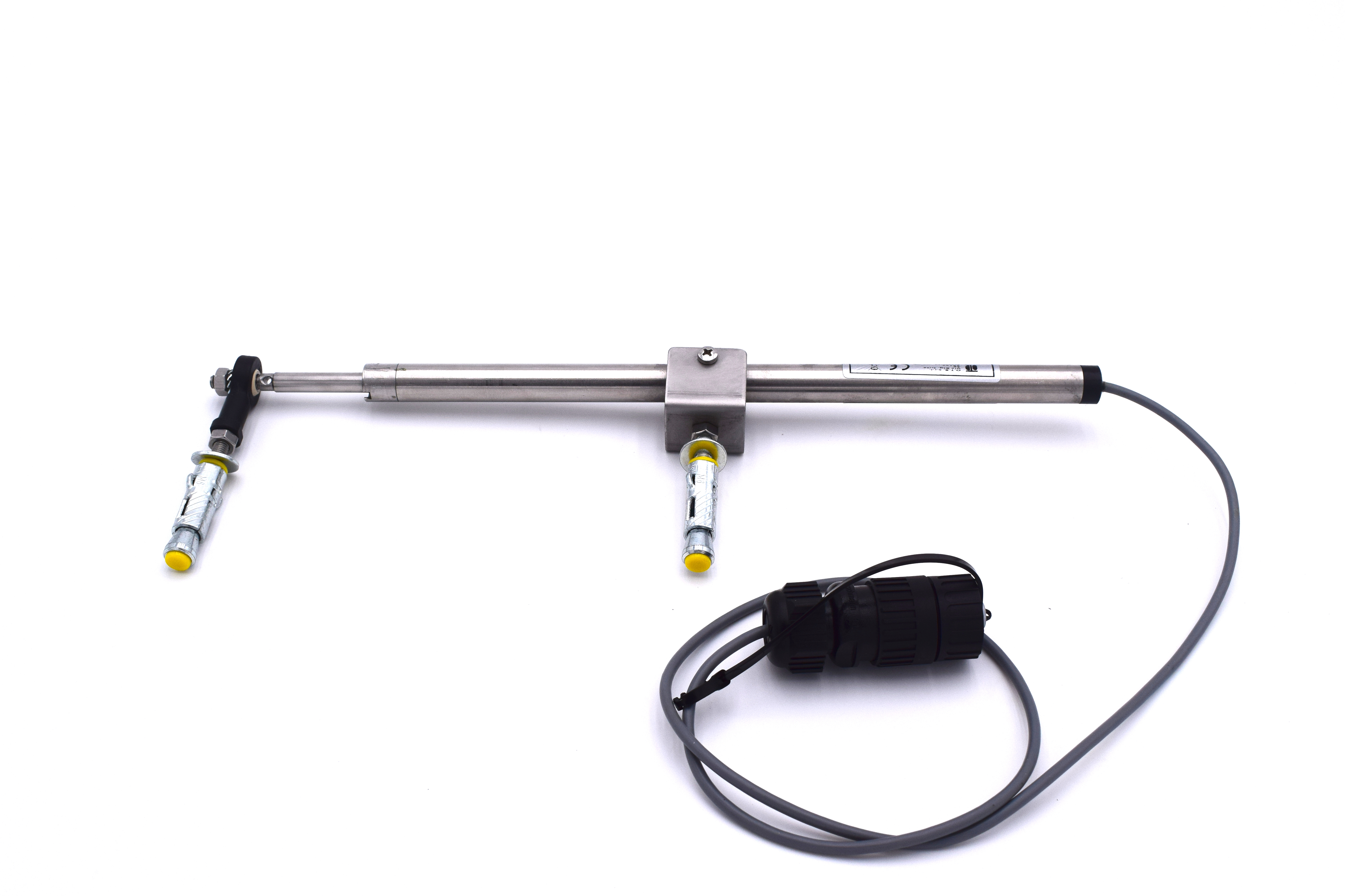
Electric crackmeter OG400
Specifications
In case of: walls and rock masses; fracture surface of civil buildings and historical monuments; bridges, viaducts and structures: structural joints in concrete dams; OTR suggest using electic crackmeter OG400.
The instrument is composed of a displacement transducer housed in a cylindrical container made watertight. At the end, the instrument is fixed to the sides with two anchors to the fracture or joint. There are various types of cracketers to satisfy every request. They can be potentiometric or vibrating wire with a wide variety of full scale. The electrical resistance of the technology is enough low to allow insensitivity to disturbances and external electrical noise even at moderate distances. After technical and commercial consultation and relative reflection by the customer, the instrument can be supplied with a manual or automatic meter, minibox and 4-20mA converter, if deemed necessary.
Installation procedure
Electrical crackmeters are supplied as a preassembled unit, therefore the installation procedure is relatively simple. The available models differ for some mechanical features, especially in the type of anchoring system for wall installation, and so the installation procedure will have to be adapted accordingly.
Before to instal the instrument, take a control reading with the readout unit, in order to establish the initial position of the instrument so as, to have a pre-set initial measurement. Normally, the instrument rod is placed at half of the measuring range.
Place the instrument and its anchoring plugs across the crack, making sure the instrument is aligned with the expected direction of the displacement and mark the position of the holes for the anchoring plugs on the wall. Then drill the holes for the anchoring plugs and insert the plugs in the holes and tighten the hex head bolts until the anchoring are completely tightened.
During the installation, take some readings with the readout unit in order to make sure that the instrument is placed as planned.
It is possible to adjust the position of the instrument even after it has been installed.
This feature is very usefull once the instrument has been on site for a while and has got towards the end of its measuring range. In that case, it is possible to reposition the instrument and bring it to the initial position by following the procedure described below.
Loosen the grub screw on the transducer’s calibration cylinder and adjust the position of the cylinder so as to position the internal measuring rod in the desired position.
At the end tighten the grub screw on the transducer’s calibration cylinder.
Remember to take measurements before and after adjusting the instrument position, in order to process data correctly.

Sede Legale
Galleria San Donnino, 4
Piacenza 29121
P.IVA/CF 00894610153
Sede operativa
Amministrazione
Direzione Commerciale
+39 347 2602151
Dott. Eligio Degli Angeli
vendite@otr-geo.it
Francesco Morgante